Welcome to the UW Midnight Sun Hardware team! Joining the team is definitely a rewarding experience, but requires time and effort in order to learn and apply many hardware engineering concepts required to building a solar car! This Hardware 101 does not require a strong knowledge in electrical circuits, but does require patience, and a desire to learn and understand how circuits work. So no matter your knowledge level, you can finish this project and learn a lot on the way.
Since it may be a bit overwhelming to jump straight into an active project for the car, it's best to start things off at a much simpler scale in order to properly grasp the design process for a board, as well as get used to the software tools for development and testing. We will be accomplishing these goals through a tutorial board that will have you ready for working on active and future board for the car.
General Description
The purpose of this exercise is to get you familiar with the following:
- Using Altium for schematic and PCB layout
- Using Jira for task tracking and Git for version control
- Reading datasheets and creating basic circuits
You will be doing this through an introductory project that is the basis of a real Midnight Sun board design used in the car.
Problem Statement:
- Control LEDs with corresponding buttons through a microcontroller → Similar to driver controls where we use buttons to control various functions of the car
- Adjust the brightness of LEDs by turning a potentiometer → Similar to reading any analog sensor data and doing something with it
IO’s:
- 2 buttons (digital input)
- 1 potentiometer (analog input)
- 2 LEDs (digital output)
Requirements:
- Buttons need to be debounced
- Use our microcontroller (STM32F072CBT6) (Controller Board Interface)
- Use appropriate GPIOs
Starting the Project
Before we get into making any circuits or PCBs, let's first make sure we understand what we need to accomplish. By reading the above description, we know we need to design a PCB that has two buttons, a potentiometer, and two LEDs. We also know that the functionality of the board is as follows: when a button is pressed, a corresponding LED should turn on. Great!
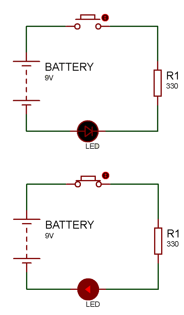
But this sounds so simple... the first google search can tell us exactly how to do wire a circuit that does this:
It's true, the underlying concept of turning on an LED with a button is simple, but we have added some requirements to this project in order to make it more applicable to our design process and to incorporate ideas that will help with design of future boards. If you remember under the requirements heading, it said "Buttons need to be debounced", and "Use our microcontroller (STM32F072CBT6)..." - Let's try to understand these requirements one by one while building a block diagram for what our circuit will look like (This block diagram will be useful when we begin to use Altium).
Creating the Block Diagram
So far we know our inputs and outputs. If we put them on a block diagram we have something that looks like:
Let's now use our requirements to complete this circuit.
Debouncing buttons:
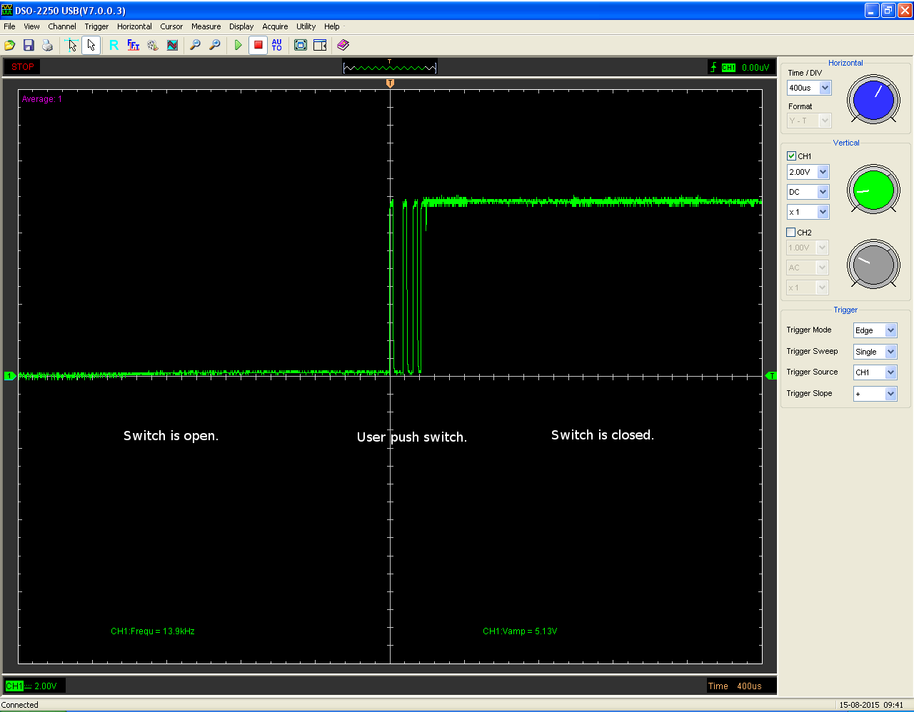
A quick google search on what button debouncing is can give you a good understanding of the theory behind why we need to 'debounce' buttons and switches. Generally, a button (the one we use for this project) is comprised of two metal contacts that complete a circuit when pressed. Unfortunately, this metal contact created by a human press is never perfect, and can create a ripple in the signal, which if not treated can result in undesirable behaviour from your circuit. This 'unwanted ripple' looks something like:
Do you see the first chunk of the signal? It goes high (on) and low (off) multiple times before stabilizing at the on position. Now, our car uses a push-to-start button; imagine that effect happening on a button like that! It's definitely undesirable, and our goal in this tutorial is to show you a couple of ways to debounce a button and obtain a clean signal from a button press.
Method 1: Low Pass Filter (LPF)
Before we understand what a low pass filter does, let's make sure we understand the concept of AC voltage/current. If you do not know the difference between the two, this link should help you. Now, notice what the unwanted voltage ripple looks like when the button is pressed: it's oscillating, which we can think of as AC voltage.
Another thing we need to understand is what a Capacitor is, and how it behaves under DC and AC. In essence, a capacitor behaves as an open circuit under DC operation, and a short circuit under high frequency AC operation (with varying degrees over a frequency range). Since our unwanted ripple voltage resembles an AC voltage at some frequency, we can use the capacitor's properties to try and mitigate this noise.
But how does this circuit shown above get rid of high frequency noise? Well, think about it - if the input signal is DC, a capacitor behaves as an open circuit, and so the bottom branch (which has the cap) will render obsolete, and Vin = Vout. However, if the input signal is a high frequency AC, the capacitor behaves as a short circuit, and now we've created a short circuit to ground, so Vout = 0. We can characterize this behaviour using a 'frequency response' plot:
Another property of a capacitor is that is takes some time to charge up under AC operation (this time depends on the value of the capacitance); and we can use this to create a 'delay' between the button press, and the signal output.


