...
The converter itself requires a solid heat dissipation strategy. Taiping was able ton secure some Vicor Heat sinks made for this model, that is placed on top of the DCDC module. In addition, the design included via stitching on the ground planes with large enough vias for sufficient heat sinking across the two planes. However after some initial testing, the heat of the module was starting to get over 100degreesC even with the large heatsink, so the plan is to place a large fan on top of the module in addition to the heat sink. (the heat sink module measures at
High Current Path
The module uses M8 wurth terminals on its outputs to handle the large current output form the board to power distribution. In addition, all the traces made on the board are copper pours with matched area for the + and - lines on HV in and out. A fuse is placed on the input rated for 8A and 420VAC. Due to the inrush caused by the bulk capacitors on the input, there is an ICL hacked on to the input terminal to fuse (the trace is cut) that will start at a cold state providing resistance enough so the current it limiting, then becomes hot enough that the resistance decreases significantly, and as there is no longer inrush current, there is less power loss from the ICL (Inrush Current Limiter). The next revision will have an active inrush current limiting circuit for increased efficiency, if it is noted that it is a problem.
Filtration
The DC Module requires certain filtration for noise due to switching and common mode on both its output and input terminals. While designing the module, the datasheet and design guide were extensively followed to ensure we were using the correct elements for effective filtration as determined by the manufacturer. The following image outlines most of the filtration as recommended by Vicor, and the rest of this page will be going over the elements we decided to use from the diagram.
Input Filtration
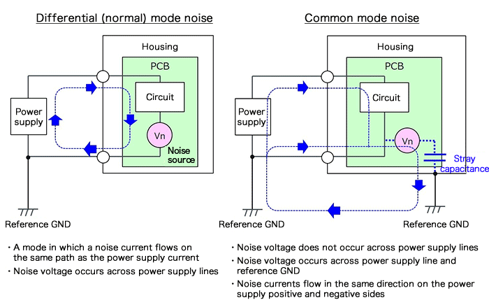
First, let's differentiate between common mode and differential noise. Both are sources of noise passed through a system's power supply lines. However, differential noise comes from noise coupled and flowing through the power lines of a supply, while common mode is the coupling of noise from the power supply and reference ground. Differential noise filters must take into account that the noise flows in either direction for the power supply lines and common mode flows in the same direction (that is, common mode noise is in the same phase on the power supply lines, and differential is reciprocal noise for each line). The following image should provide a better picture.
Anyways, we decided to make our filter include the y-caps as suggested due to the effectiveness of y-caps to common mode noise. We also included the emi optional filter using the common mode choke as an extra precaution for common mode noise. In terms of possible differential noise, we included the LCR (inductor-capacitor-resistor) filtration circuit as suggested by Vicor on the datasheet for the input.
Output Filtration
Similar to the input filtration, we added a LCR filtration circuit as suggested on the datasheet for the differential mode noise. For the common mode noise, we once again added the y-caps (that essentially are meant to be symmetrical in terms of capacitance and distance to the nodes on the module to filter the common noise equally and at the same time) without adding the optional emi filter, as the extra precaution for the common mode noise was not suggested on the output of the module.

